11. I can't unlock E-Gold phones via testpoint, what is the problem?
Please read troubleshooting section.
12. I have performed the TestPoint procedure for Sony Ericsson handset. Do I need to perform the TP connection again for that specific phone?
The TestPoint access mode has to be performed when the phone is connected for the first time. All future connections for the same phone have to be performed using "Security Bypass" access mode.
13. How to upgrade DreamBox Plus to DreamBox SE?
In order to get DreamBox Plus upgraded to the DreamBox SE please enter the activation code to the DBSS and within one hour perform box firmware update process. For more information please check How To section.
14. Executing of "Security Bypass" operations failed at the Stage 2. Do I have to repeat the process from the beginning?
It may happen that during the "Stage 2" of executing ""Security Bypass" the operation fails to complete. In this case please repeat the process for the "Stage 2" only. Unmark the option "Stage 1" and perform the process again.
15. At the moment in the GSM market there are 2 DreamBox hardware types: the old and the new. How can a user define the hardware type of his DB?
It is pretty simple. Please take a look at the device's USB connector: connector Type А indicates the older version, while connector Type В � the new one.
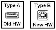
Figure 1
16. What is the functional difference between the DB with the new hardware type and the old one?
Devices with the old type hardware do not support automated indication of the TP needle contact with the Testpoint (TP), i.e. the software will not produce any visual/audio signal when you touch the TP with the needle. Therefore, while working with the old type hardware DB, you will have to touch the TP and press "Start" button while holding the TP needle until the program prompts to remove it (Figure 2.)
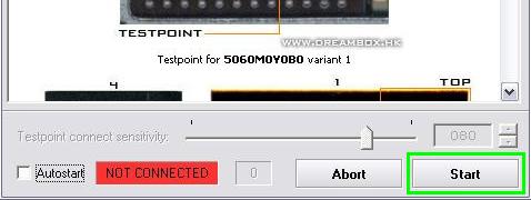
Figure 2
17. Which advantages are offered with the new hardware type?
To enable the program to work automatically, the user should tick the Testpoint Autostart option of the Sony Ericsson tab in program settings or Autostart option in TP dialog box (Figure 3).
Working with the new hardware type, the user just has to touch the corresponding TP on the flash memory chip. The connection of the needle with the TP launches the automated detection procedure, indicated by audio signal and TP connection indicator becoming green (Figure.3). Then it is important to hold the stable connection between the needle and the TP (usually for 3-5 sec), untill the software informs with a short audio signal (beep) and a message in the dialog box allowing to remove the needle from the TP.
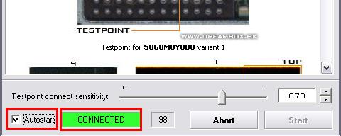
Figure 3
18. How to choose the right TP schematic among the numerous variants?
The TP schematics show flash memory chip's leads and the TestPoints located there. However � there are alternative TPs for the same model (TP1 or TP2). These alternative TPs help the user to skip the access under the chip, allowing him simply to touch certain chip's substrate lead with the needle. To avoid misunderstanding, please perform the following steps:
- Define which type of the flash memory chip is on the PCB, as there are three types of DB2020 platform chips: Intel_5060M0Y0B0, Intel_5060M0Y0BE, and ST_M39P0R907.
- Define which type of substrate is under this flash memory chip (every type of the flash memory chip mentioned above has two types of substrate produced by different factories); in order to do this the user has to compare the TP pictures with the chip appearance using a microscope.
- Select the indicated substrate lead and touch it with the needle according to the DBSS instructions.
- It is also preferable to upgrade the TP adapter by replacing the standard needle (default solution) with a thinner one, e.g., beadwork needle. For hard-to-access TPs (e.g., in W710 or Z710 models) please, use a special TP needle with a bent end. Such a needle is absolutely necessary when the chip is tightly adjacent to the protective shield that must not be removed, or there is a component located very closely to the chip and therefore may be damaged with a straight needle.
19. What will happen if I mistakenly touch the wrong TP?
In this situation neither the phone nor the DB are in danger, except for the cases when the user touches simultaneously the TP and a component (meaning the mounting lead of the component), responsible for power supply in the phone (capacitor, resistor etc.). This way the TP, i.e. the flash memory chip, may be shorted or exposed to a voltage surge. In the latter case the chip, phone's processor or the shorted component may get burnt.
In order to avoid the above mentioned problems, we recommend to replace the TP needle with a thinner one (see Answer 18.4 above)
20. Why the TP connection indicator is always green?
Most probably, the TP connect sensitivity is set to 100%. Sensitivity slider should be placed at around 70-80%, the optimum position is 70% (Figure 4).
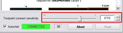
Figure 4
Also, such a failure may be caused by a defective or damaged TP-adapter v. 2.0 (i.e. TP- adapters with logic control inside). To solve the problem, the user should disassemble TP-adapter and make sure that PCB components are properly mounted; it is desirable to solder these components once more, paying special attention to U1 component (Figure 5).
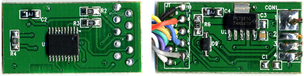
Figure 5
0 comments:
Post a Comment